
3D Printing Flying Probe Test Harnesses: Can you?
Introduction
While testing a client's device, I found it included a castellated board with non-standard pitched castellations. I had a lot of trouble probing the castellated component with SensePeek PCBites and other styles of probes.

Printed Circuit Board with Castellated Edges
Whether due to falling over hours after being set, or being bumped out of place while setting a subsequent probe and ultimately shorting a voltage regulator and bricking a device, I became desperate for a better solution. Because of this frustration, I started tinkering with designing an assembly to hold the PCBites in place before remembering my stash of pogo pins and sleeves, and instead began designing a harness to hold pogo pins at the non-standard pitch for the target. While the test ended successfully before the need for that assembly, the idea stuck all the same.
What Are Probes (I’ll Keep This Brief).
Electronics are commonly tested at time of manufacture using a process called Flying Probe Testing. The probes used for these tests are manufactured in a variety of formats, but generally consist of a sleeve and spring loaded pin. In automated testing, these probes allow for some wiggle room in clearance when moving to contact circuit boards or components which might have varying dimensions.

Flying Test Probes
While suited quite well for their intended purpose, spring loaded test probes, or "pogo pins" have seen an increase in popularity over the last couple of decades. Uses range from small-run console modchips to charging station contacts to handheld testing probes. As implementations like these have hit the scene, they have spurred a lot of innovation.


Why would we want to make our own?
The use case of interest for this project is the assembly of target-specific probe harnesses. While tools like sockets exist for various formats of components, such as flash chips or MCUs, the practice of designing custom System-on-Module (SoM) boards with castellated edges for mounting and connection to the main board has become more common, and there is generally no common socket for these types of boards.
In some cases, when such a board features a common pitch such as 2.54mm, it is possible to assemble sockets to suit them using special components such as Solder Party’s FlexyPin.

Castellated Board Mounted with FlexyPins
However, hardware designers do not always use standard pitch for board-to-board connections, even when using otherwise standard footprints for castellations.

Non-Standard Pitch or Depth Castellations
When encountering these patterns of design in hardware assessments, existing solutions such as PCBite, or generic air nozzle-based third-hand devices become cumbersome and self defeating. With each probe added, the chances of knocking an already bitten probe over increase, which could and has resulted in shorting components and bricking a test target. Obviously, this is something we would want to avoid when performing testing, especially on a client's dime and time.
For cases such as these, the appeal of designing a probe harness is significant, however, acquiring such a harness is very likely impossible. Even when clients can provide engineering or debug builds of products, it is very uncommon for them to have it in their contract for their manufacturer to also provide them one of their own flying probe assemblies, and even less likely that the assembly would be designed to contact all traces from a given major component in the first place.
The advent of affordable 3D printers begs the question of whether it may be possible to design and manufacture test probe harnesses for uncommon targets in-situ. In this post we will go through some approaches taken to try to answer this question, including what did not work and what might work better next time.
SLA vs. FDM and the Expected Challenges of the Latter
While SLA (Stereolithography Apparatus) printers seem quite well suited to this purpose, they are also expensive to operate and messy. I personally do not own an SLA printer for these reasons, and order out for resin prints when I want them. This, however, takes weeks usually! FDM (Fused Deposition Modeling) Printers are cheap, widely available, and the materials they consume are also quite affordable.
Despite these advantages, FDM printers also come saddled with several disadvantages for this purpose. Most likely you will be printing with a .4mm nozzle, which will introduce challenges in slicing. FDM printers struggle to make corners without loss of dimensional accuracy due to expansion and shrinking of the printed material, especially when laid in the motions made by the printer to achieve a corner. Similarly, the printer must have flow, extruder steps, x/y skew, and print speed tuned in order to achieve dimensional accuracy.


Some of these disadvantages must be worked around, while others are more a function of how well your printer is tuned and maintained. Ordering such a part from an FDM shop may result in better or worse accuracy than you can achieve on your own with a little tuning, and it is likely if you are 3D printing already that you may have already undertaken steps to tune your printer.
By leaning on lessons learned from general 3D printing, the advantages of the speed and accessibility of FDM printers could be maintained by designing for the strengths of FDM printing rather than languishing in or attempting to design around its weaknesses. Care taken in tuning wall thicknesses, layer heights, flow, extrusion, thermal expansion offsetting, mesh bed leveling, vibration compensation and other features and settings can mitigate or even eliminate many of the disadvantages of FDM printing in our use case. That said, care must still be taken in the design of the model itself to ensure the strengths of the printer are exploited while the weaknesses, such as inability to print accurate corners, are avoided or eliminated altogether.
Plan of Attack
In order to determine the efficacy of this approach, I brainstormed a few different harness styles and chose the ones I thought would be most accomplishable at the outset. After developing a plan for harness styles, I gathered documentation and materials relating to the target device as well as the pins and sleeves I had on hand. Once materials were gathered, I rapidly printed and tested several design styles and documented what did and did not work with each including those ever-anticipated, unforeseen issues so commonly encountered when printing.
Preparation / Setup
Equipment, Tools, and Software I Used
CAD - Audodesk Fusion 360
For the design facets of this project I used Fusion, but any 3D modeling software you are comfortable with would be just fine! I have successfully used tools ranging from Tinkercad to Blender to Fusion to produce models for 3D printing, it all comes down to what works for you and whether it will facilitate precise dimensions in design.
Slicer - Cura
I chose Cura for slicing models for this project because I am most familiar with the nomenclature of the settings, which are crucial in this project for achieving dimensional accuracy. Again, this is not a requirement for your own purposes, any slicing software which allows you to achieve high dimensional accuracy would be fine.
Print Controller - Octoprint + Obico
I still use Octoprint because I find its plugin approach the easiest to work with in order to implement my enclosures’ sensors and relay controls. In addition to various sensors monitored directly by the printer mainboard and Octoprint via Raspberry Pi GPIOs, Obico is also used to monitor the print job from various cameras and automatically detect failures. It is important to note that modern printers have directly implemented many of these features and more.
Printer - Creality "Ender 3 Pro" (kind of)
The printer used for this project was originally an Ender 3 Pro, but has undergone enough modifications since 2014 that it is easy to question how much of the original printer remains. In this case, a dual-Z axis FDM printer configured for bowden extrusion with a high-temperature hot-end and automated bed leveling. For comparison, an untuned Bambu Labs A1 Mini was also used to print some of the prepared models.
Pins and Sleeves - R-50 Sleeves and P-50-B Pogo Pins


Which Target to Design For
I needed to select a device with a similar pattern of castellation In lieu of any customer's device. I cannot violate NDAs no matter how cool. I had a few in mind, but decided to explore a couple of options in case my first idea did not work out (it did not after all).
ESP32 SoM


Having used various patterns of ESP32 development boards dozens if not hundreds of times, I thought first of these devices for a facsimile to the original target which inspired this project. These devices include a castellated ESP32 SoM with sub-1.27mm pitch, which is too small to easily achieve a working probe as the width of even the internal pogo pin sleeves is too wide to align side-by-side.
Some efforts were made to achieve a design for this using a sort of X or criss-cross pattern of alignment for the pins, however this seemed too cumbersome to pursue first. This remains a desirable target due to the common pattern ESP32 SoM's immense ubiquity in consumer products such as the Hatch alarm clock pictured above, as well as commercial and industrial products alike.
To wit, occasionally you will find more uncommon patterns for ESP32 SoM boards, such as in Sainsmart weather meters as pictured below.

Uncommon Pattern ESP32 SoM
WaveShare ESP32-S3 Zero

WaveShare ESP32-S3 Zero
WaveShare produces a lot of products. Most of the time when I encounter one of their products as implemented in something else, it is a display. I have not yet encountered a WaveShare castellated ESP32-S3 SoM in the wild to date. With that all said, the 2.54mm pitch makes it an easy target for demonstration, however it is extremely uncommon compared to the pattern found on WROOM/WROVER/everything-with-wifi+bluetooth-you-crack-open.
An advantage of targeting this pattern worth mentioning is the lack of a third row of pins to probe. This type of pattern would be an ideal target for a clamp-style probe harness.
WaveShare RP2040 Zero
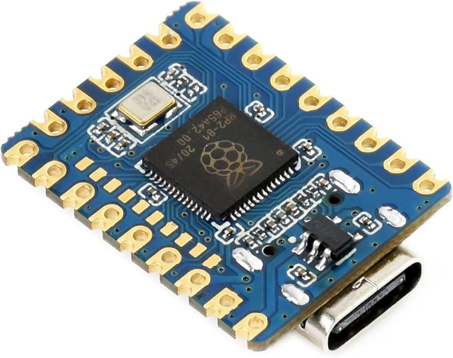
WaveShare RP2040 Zero
Almost the exact same pattern as their ESP32 Zero board, WaveShare's RP2040 castellated board also sports a 2.54mm pitch. Though I have not seen this pattern for an RP2040 in a product in the wild, nor any RP2040 yet, this specific model seems to be a fairly popular pattern for the RP2040 among Maker types based on casual searching.
For the purposes of this project, we select this board for our target. Note that the target is not necessarily what is important here, but rather whether or not this approach is viable for use in real world scenarios.
Designs

Wasted PLA
During the brainstorming phase I came up with several ideas for what styles of harness might enjoy the advantages of FDM printing more than grate against its weaknesses. Coupling those constraints also with a presumption that the simpler the design of the model itself is, the better. This resulted in setting aside designs which involved torsion springs and other mechanisms, such as clamps. This also precluded at the outset the use of compliant mechanisms, which would likely be a solution worth pursuing to one of the caveats encountered during this project.
Ultimately, I decided to pursue a simple Block-with-Holes design as this seemed to be the most simple design possible. As discussed later, however, this design introduced challenges which I had not anticipated. In light of those challenges, I ended up abandoning the block design in favor of another option, a Block-and-Compression Ring, mid-way through the project.
Box-with-Holes

Partially Assembled Probe Harness
Designing for the target
Where to point the pins
If your target has footprints available, lucky you! You could import those into your CAD software and use them to trace the outlines of your model and take Easy Street to your destination.


If your target does not have a footprint, because it is not a consumer product but just some weird thing you found inside the plastic and maybe they drew the pads by hand, then you will need to turn left and take The Hard Way.


Little things
We can take advantage of the play afforded by the spring-loaded pogo pins to design a harness which will have some amount of grip on the target board. To do this, we can angle the slots for the pins inward at the bottom by a few degrees. In this case I chose 92 degrees as the angle for the pin slots, which I intended to result in having all of the pins somewhat compressed by friction against the vertical edge of the castellation.

Angling Pinholes
Here I thought I was being quite clever in attempting to design the model such that the slicer would create discrete circles for the holes in the model. My thinking during this process was that by slicing the holes as discrete individual circles, the best dimensional accuracy could be achieved, resulting in the ability to print a model which would accept the R-50 sleeves in a friction fit. Since using techniques otherwise viable for achieving friction fits in 3D prints such as expansion channels or increasing and lining the bore with flexible fins was not possible here due to the constraint of the .4mm nozzle size.


I initially used a .88mm hole to afford a very small clearance for the ~.86mm width of the R-50 sleeve and included a 1mm counterbore, which I had hoped would leverage the ridge on the end of the sleeve to increase friction for the fit.

Designing the Counter Bore
Immediately, the first major unforeseen caveat became apparent.

Top View of Diminishing Hole Size Along Rows
Attempting to print this model with an untuned Bambu Labs A1 Mini did not yield better results.

Holes Near Completely Sealed
All of my clever forethought about ensuring the circles laid down for the pin-holes were discrete was for naught. This created an issue wherein the constant hopping and retraction while printing the circles created a buildup at the nozzle which overpowered the static thermal expansion compensation. Thinking that it would be easier to just jam a .9mm needle through the holes to widen them rather than manually edit the G-Code for the print to increase the compensation to the flow setting along each row of holes, I carried on.
It soon became clear that this approach was not good for rapidly producing a usable harness. Even for the holes which seemed to have the best dimensional accuracy, it still required applying pressure to a delicate brass or copper sleeve. Attempts to assemble this version resulted in the loss of many good sleeves in crush accidents. Still some holes were too wide, and others too narrow, which seemed like too much delicate effort for something that was intended to be easier and faster (and cheaper) than existing solutions. It was getting dark, and I was starting to run out of pre-soldered sleeves.


At this point I tested increasing the width of the holes at the ends where they were becoming too narrow, and considering using a material like thread or magnet wire to shim the holes to achieve the friction fit I intended. Seeing no success in adjusting the hole diameters, or adding additional holes in the hopes that the effect would be pushed out to them instead, I decided to pivot to a different design.

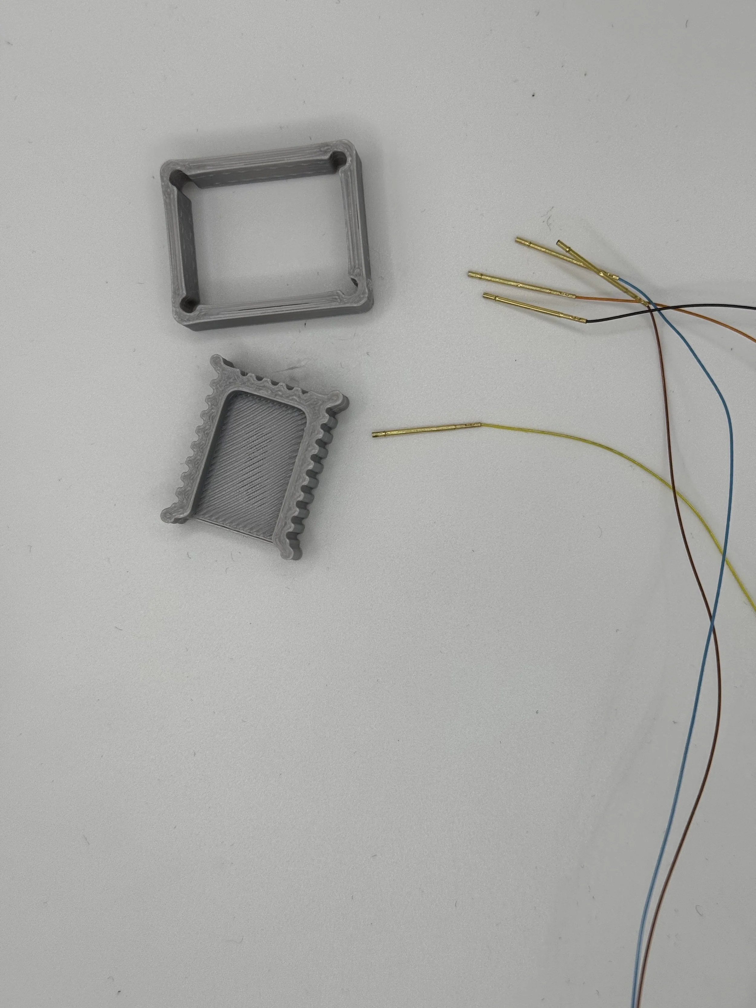
First Layers of Box versus Compression Ring Designs
Compression Ring
I did not want to give up on printing a model which achieved a friction fit without a third material to shim. The other of the two designs seemed more complicated in that it would be two pieces which risked issues with clearance and fits. Despite that caveat, the two-piece design also afforded more flexibility in the friction applied to the pins, or so I had hoped.


Design changes
Using the previous model as a starting point, I divided the model along the center axes of the rows of holes, and increased the distance of the edge-faces between each of the lengths of the former-holes to create more U-shaped channels. I also added dowels at 90 degrees to the interior corners where the two models combine in order to provide a constant friction not afforded by the +2 degree angle of the channeled faces. A clear advantage of the compression-ring style is that it is sliced as almost entirely unbroken lines, resulting in a significantly faster print. While the block-and-hole style harnesses were taking 40-50 minutes to complete, the compression ring design only took about 17 minutes.


After several iterations of this model, including attempting to add studs and bars to the interior of the compression ring at each pin, I found myself back to considering using glue, or some kind of shim material, to achieve a snug fit for each sleeve inside the model.

While I was impressed with the level of dimensional accuracy I was able to achieve with a .4mm nozzle and a decade old FDM printer-of-theseus, sub-milimeter features seem to be very difficult to print successfully.


Well At Least We Learned Something
Using some simple glue, I went ahead and assembled a full model and performed a basic test, flashing the RP2040 and making it blink using the harness and a [????] programmer.


While there were a few setbacks before reaching this point, none were so severe as to deter me from considering this approach in the future. The capability to design and manufacture bespoke probe harnesses to drop a single assembly into a target and probe all exposed interfaces in-situ within the span of a day or two is still highly appealing, even if it means using a little glue.
Conclusions
FDM printers require a lot of tuning to get close to decent dimensional accuracy. If the pitch of your target is too narrow, it will be difficult or even impossible to achieve a design which can be printed without using a staggered and criss-crossing approach, which further increases the complexity of the print. An SLA printer is going to outperform an FDM printer for these purposes, but these are not as approachable with an FDM printer.
While this seems challenging, I am excited to explore possible options to achieve this going forward. One good option for this is designing for bare pogo pins and shimming them in place with the lead wire as demonstrated below. Another approach might be to abandon pogo pins altogether and opt instead for solid-core copper wire which can be used to achieve clean prints for smaller pitched targets.
Despite these caveats and those which come along with attempting to FDM print any object, it still seems a viable method for designing probes even if a third material such as glue or shims are needed for a snug assembly.
With some lessons learned, particularly about how better to design the channels or holes for pins, I wanted to demonstrate the efficacy of FDM printers for rapidly developing test harnesses. To do this, I grabbed a D-Link router from the To-Hack pile, cracked it open and located an unpopulated interface. Within about one hour, including print and assembly time, I was able to prepare, apply, and use the harness.


If you want to give these models a try yourself, copies of the .obj files are available on Sam’s GitHub.
Looking Forward
Some caveats for this style of probe harness might be overcome by using a narrower nozzle, such as .2mm, which I believe is worth exploring in the future.
In addition to this single-block style of probe harness, I think there is also value in the use of FDM printers to produce clamp style probes for common formats like SOIC8, as well as Electronics Acupuncture Probe (EAP) assemblies, which I look forward to experimenting with soon.